Description | Setup | Initial Results | Next Results | 12" Gyro Results | Next 12" |
C1 Results | Next C1 | Final C1
Description:
To independently verify that
the centrifugal force of a precessed mass is less then a non
spinning mass moved through the same motion. The experiment will use a
different methodology then the 'heretic' experiment completed by
Bill Dawson and the late Professor Laithwaite but should show the
same result. The experiment will also verify that the
effect can be used for propulsion where a precession
phase is matched with a translation phase, in this case both
happening continuously and at the same time.
Method:
Step 1. Test
Apparatus Overview
A test apparatus, C0 shown in
figures 1, 2 and 3, will be built:
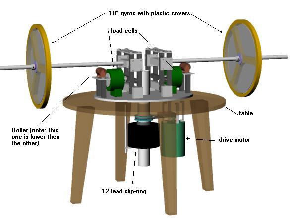
Figure 1: C0 Test Apparatus

Figure 2: Close up of Anchor Assembly and load cells on Main Platform
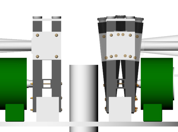
Figure 3: Degree
of Movement of the Anchor Assembly
Figure 3a: Or See Video
(2meg MPEG4)
Legend:
Arm assembly
- allows the gyro to move up or down and to be pulled outward by
centrifugal force.
Main platform -
the elliptical circular platform which can rotate
Central axis
- the axis about which a gyro is precessed or translated.
Gyro axis - the axis about which the gyro spins.
Note this axis moves with the gyro around the central axis.
Central Torque axis - another type of 'twist'
but centered at right angles to the central axis. A torque
is applied around this axis which creates precession about the
central axis. Note this axis moves with the gyro around the
central axis.
Forced Precession - a generated torque not
centered about the central axis.
Precession - The result of an applied torque
which moves the gyro around the central axis. The
device will consist of two 10" diameter
free-spinning gyroscopes covered with plastic covers (to
reduce air friction) and each gyro will be connected by
a 1/2" dia. high-tensile strength steel (C1018) rod to
the anchor assembly. The anchor assembly will allow
the gyro to swing up or down (except if supported by a
roller) and forward/backward while pressing on a load cell
button measuring a scaled centrifugal force. The gyro(s)
will be spun up by an external electric motor not shown. The
gyros are can move up/down to allow gravity to
apply a vertical torque, shown as a large gray #1 arrow
in figure 4, which results in a torque at right
angles (precession) shown as the large red #1
arrow. By rotating the main platform at the same time,
a horizontal torque, shown as a smaller gray #2 arrow in
figure 4, will create another torque (partial forced
precession) shown as the small red #2 arrow which will
be used to keep the precessing gyro horizontal.

Figure 4:
Applied and Generated Torque with Partial Forced Precession
Step 2. The load cells will be
calibrated for zero load.
Step 3. The
baseline experiments will be done as described after the
Methods section.
Step 4. Primary
Experiment: As shown
in figure 5, the gyro, whose roller is not touching,
will be spun up and precessed by allowing gravity to apply a
vertical torque and at the same time, the central housing will
be rotated until the precessing gyro is
horizontal. The other gyro will not be spinning and will
rest on it's roller. Once the precessing gyro is level with
the translational (non-spinning) gyro and a number of
rotations are completed, this will be the steady state and a
measurement from each load cell will be taken and compared.
Figure 5:
Animation of Motion
Baseline
Experiments:
A. With both gyros not
spinning and held horizontal, the central housing will rotate
around the central axis and both gyros should exhibit the same
centrifugal force.
B. With both gyros spinning
and precession initiated, the central housing will rotate around
the central axis and both gyros should exhibit the same
(reduced) centrifugal force.
Expected
Result:
During steady state, as
defined in methods:step 4, a difference in pressure on the load
cells will be measured.
If the result is as expected,
then it will show how significant the difference is between the
calculated and measured centrifugal force which will give us an
indication of how powerful a propulsion device can be built. In the
event no difference in centrifugal force is measured then an
alternative method of propulsion will be researched.
May Adversely
Affect the Result (MAAR):
Concerns/Remedies:
The rotation of the gyro about the gyro axis will not be powered and will start to drop from horizontal as it slows down.
To keep the gyro horizontal, the rotation speed of the main platform will be slowly increased and a plastic cover will be added to reduce air friction.
The measured centrifugal force will be scaled up because of the lever effect of the anchor mechanism.
The measurement is concerned only with the difference and the baseline experiments should solve this MAAR because they will show what centrifugal force a non-spinning gyro produces.
The load cells are only rated for 50lbs which may be too small.
A load cell capable of handling 200lbs is standing by.
It could be claimed that the air currents from the spinning gyro is what causes the reduction in centrifugal force.
A second experiment is possible whereby a box is fastened around the gyro to remove this possibility.
One side might weight more then the other.
The baseline experiments will show any differences between each side and care will be taken during fabrication to ensure symmetry.
If the difference is large, the table may wobble.
Great!
Description | Setup | Initial Results | Next Results | 12" Gyro Results | Next 12" |
C1 Results | Next C1 | Final C1
JumpDrive Confidential, 2002 - All right reserved, no part of this document may be reproduced without the authors permission.