Description | Setup | Initial Results | Next Results | 12" Gyro Results | Next 12" |
C1 Results | Next C1 | Final C1
Setup and Specifications of Test Equipment
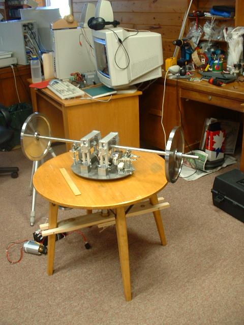
Figure one shows the test setup used to take the measurements.
Figure 1: Test Setup
The setup consist of:
The finished C0 test apparatus is shown in figures two and three.
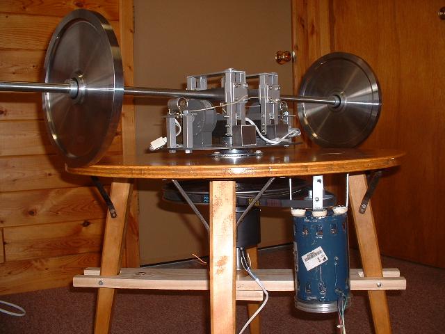
Figure 2: Side Shot of Finished C0 (Note: Two Lebow Load Cells shown)
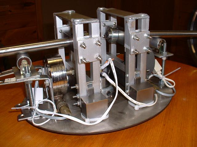
Figure 3: Close up shot of Main Platform
Each gyro weighs about 4 to 6 pounds and has been machined to the dimensions shown in figure four.

Figure 4: Cross Section of Gryo (rendered)
The C0 Test apparatus consist of the following parts:
The only major difference between the experimental description and the actual setup was the shape of the gyros. It was simpler and safer to create a gyro without spokes.
The data collection software consists of a heavily modified UEI example program written in Visual Basic 5.0, where figure five shows a screen shot.
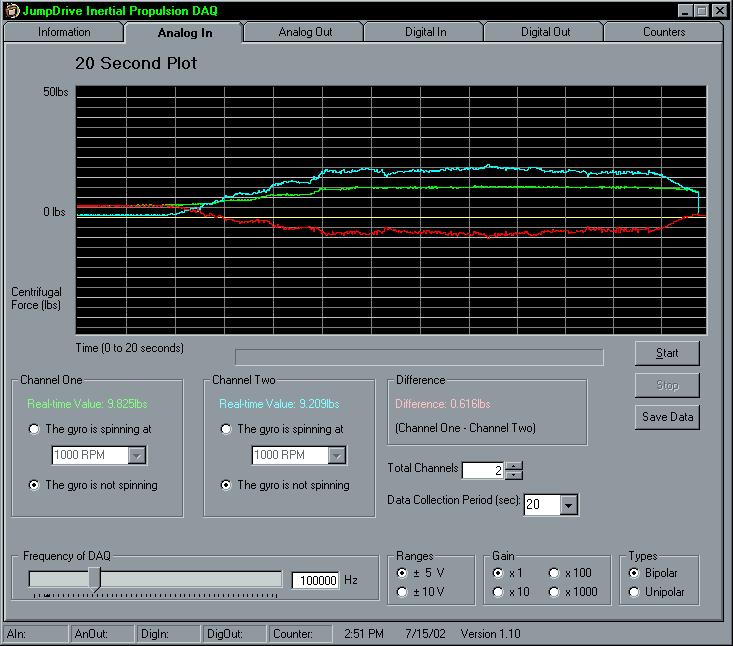
Figure 5: Software Screen Shot
The software was modified to display two channels including a difference measurement for a collection period anywhere from 1 second to hundreds of seconds which could then be saved as raw data.
Description | Setup | Initial Results | Next Results | 12" Gyro Results | Next 12" |
C1 Results | Next C1 | Final C1
JumpDrive Confidential, 2002 - All right reserved, no part of this document may be reproduced without the authors permission.