Description | Setup | Initial
Results | Next Results | 12" Gyro
Results | Next 12" |
C1
Results | Next C1 | Final C1
1. Summary of Results
The results are inconclusive
because too many serious measurement issues exist.
2. Introduction
Included in this section are the two
baseline measurements and then the primary experiments where one
variable is modified. The variables modified are:
- "G" or gyro variable - Only
one gyro is is being partially forced precessed while the
opposite one is still
- (NOT DONE YET) "R" or
rotation variable - The starting rotation speed of gyro
is varied from 2000RPM and up
When one variable is being varied, other
variables should be held constant and they are the:
- Main variable - Speed of rotation of
main platform. Because the speed at which the gyros spin
slowly decreases, it is necessary to increase the
rotation speed of the main platform to keep the gyro(s)
horizontal (unless otherwise specified). The
"Main" variable is important because it is the
point where the baseline results can be compared to the
primary results, in other words, during the primaries,
the main platform is rotated only up to the speed where
the non-spinning gyro centrifugal force matchs a
baseline.
- Angle variable - This designates
whether the precessing gyro started out horizontal or at
'n' degrees below horizontal.
- (NOT DONE YET) Diameter variable - The
10" diameter gyro is replaced with a 12"
diameter gyro.
Notes:
- Step 2 of the experimental description was not done, in order to avoid changing
the raw data as much as possible.
- Although the video only lasts 20
seconds due to hardware limitations, it is vital to see
what the gyro is doing to interpret the results
correctly. Specifically to answer questions like is the
gyro bouncing or is the gyro horizontal?
- Each measurement consists of three
sets of data:
- Graphed data - a screen shot
of the results as shown on the customized
software
- Raw data - a text file with
all three channels (one, two and the difference)
recorded in comma delimited fields
- MPEG video - a 20 second
MPEG-4 format video
Each test run is recorded with a certain
file name which is as follows:
"[Variable][Depends on
Variable][Angle]_[Test Number]"
where,
- [Variable] can be "G" for
Gyro, "R" for rotation speed or "B"
for Baseline.
- [Depends on Variable] is :
- If [Variable] is "G"
then this field is either channel "1"
or channel "2" which means either
channel one or two has the precessing gyro.
- If [Variable] is "R"
then this field is the rotation speed of the nth
gyro, for example, "2K2" means the
second gyro is rotating at 2000RPM or
"3K2" for the second gyro rotating at
3000RPM, etc.
- If [Variable] is
"B", then this field is the centrifugal
force of channel one (10, 20, 30 or 40) and an
"S" modifier if both are spinning
- [Angle] is "0" for
horizontal or "n" where n is the degree the
axle started from horizontal
- [Test Number] can be "00" to
"nn".
For example,
- "R_4K2_25_10" is where the
rotation speed of the second gyro is 4000RPM which
started out at roughly 25 degrees below horizontal and
this is the tenth test result. The first gyro is assumed
to not be spinning and held horizontal.
- "B_20S_0_00" is a baseline
experiment, both gyros are spinning and the aim is to
record the results when both are horizontal and one
channel is registering 20lbs.
3. Baseline Results
These results correspond to step 3 in the
description and are run with the following static variables:
- Gyro rotation speed: 2000RPM (if
spinning)
- Gyro diameter: 10"
- Angle: Horizontal
Non Spinning Horizontally Held
Gyros
~10lbs on Channel One
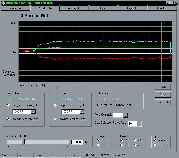
Raw Data: "C0 - B_10_0_00.txt"
(Contained in "Baseline Raw Data.zip)
Video: "C0 - B_10_0_00.mpg"
(1.7MB MPEG4 compression)
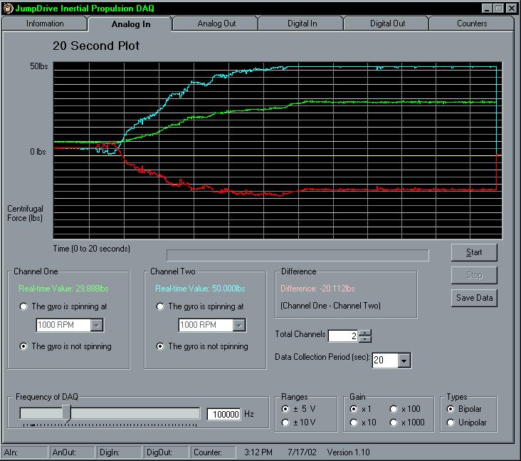
~20lbs on Channel One

Raw Data: "C0 - B_20_0_00.txt"
(Contained in "Baseline Raw Data.zip")
Video: "C0 - B_20_0_00.mpg"
(1.7MB MPEG4 compression)
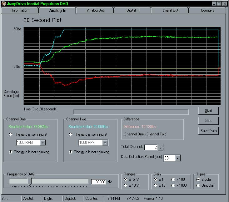
~30lbs on Channel One
Raw Data: "C0 - B_30_0_00.txt"
(Contained in "Baseline Raw Data.zip")
Video: "C0 - B_30_0_00.mpg"
(1.7MB MPEG4 compression)
~40lbs on Channel One
Raw Data: "C0 - B_40_0_00.txt"
(Contained in "Baseline Raw Data.zip")
Video: "C0 - B_10_0_00.mpg"
(1.7MB MPEG4 compression)
Both Spinning Horizontally Held
Gyros
Note: The speed of the main platform was
run at the speed required to keep the gyros horizontal.
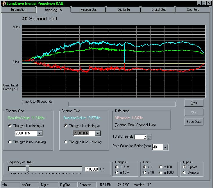
Raw Data: "C0 - B_S_0_00.txt"
(Contained in "Baseline Raw Data.zip")
Video: "C0 - B_10_0_00.mpg"
(1.7MB MPEG4 compression)
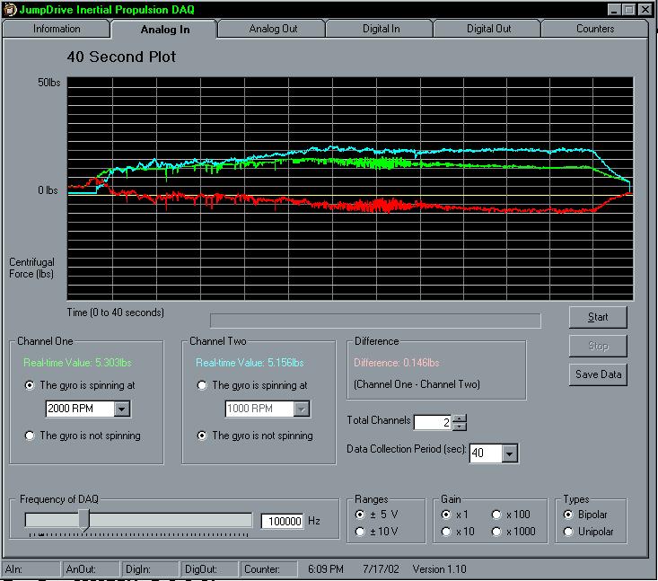
4. Primary Results
The primary results consist of altering one
variable at a time and each time, two separate measurements are
taken.
For all the primary results, the following
static variables apply:
- Gyro rotation speed: 2000RPM
- Gyro diameter: 10"
- Angle: Horizontal
- Main platform rotation speed is such
that when
channel one is precessing, 20lbs is the target for
channel two (which is
not spinning) and when channel two is precessing (as
in G_2_0_00), the target for channel one is 10lbs. These targets are per the 10lbs
baseline and no higher
pressure was done.
Gyro Variable, Channel One
Gyro 2000RPM - G_1_0_00

Raw Data: "C0 - G_1_0_00.txt"
(Contained in "Raw Data for Gyro Variable.zip")
Video: "C0 - G_1_0_00.mpg"
(1.7MB mpeg-4 compression)
Gyro Variable, Channel One
Gyro 2000RPM - G_1_0_01
Raw Data: "C0 - G_1_0_01.txt"
(Contained in "Raw Data for Gyro Variable.zip")
Video: "C0 - G_1_0_01.mpg"
(1.7MB mpeg-4 compression)
Gyro Variable, Channel Two
Gyro 2000RPM - G_2_0_00

Raw Data: "C0 - G_2_0_00.txt"
(Contained in "Raw Data for Gyro Variable.zip")
Video: "C0 - G_2_0_00.mpg"
(1.7MB mpeg-4 compression)
Gyro Variable, Channel Two
Gyro 2000RPM - G_2_0_01

Raw Data: "C0 - G_2_0_00.txt" (1 KB text file) A bug in
the software did not allow the raw data to be saved.
Video: "C0 - G_2_0_01.mpg"
(1.7MB mpeg-4 compression)
5. Analysis
Unfortunately, the test data indicates the
measurement apparatus is not dependable enough to take accurate
measurements.
The first thing is that when the apparatus
is at rest and even though the gyros are both horizontal and the
arm assemblies are almost identical, the load cells register a
difference which also shows up in the baseline results when the
main platform is spinning. Another problem is that for some
undetermined reason the at-rest difference changed between when
the baseline and primary tests where done.
There are a number of suspects as to why
such a difference exists, the first being that, although both
load cells have the same specifications, 50lbs, same output
voltage, bridge type, etc, they are manufactured by two different
companies. They may also be affected differently by temperature
which have been ranging �10degrees these past couple of days.
The second suspect is the different flexibility of the supports
for the load cells because, as shown in setup, the Sensotec load cell has a different mount which
flexes slightly more then the Lebow load cell mount.
The difference could be removed by adding a
constant in software to one or the other channel when the device
is at rest and the gyros are horizontal, in other words,
calibrate the measurement system.
Even with the above difficulties, the data
is encouraging because if the primary graphs (G_1_0_nn and
G_2_0_nn) are studied closely, you can see the last 20 seconds of
data has a discernable slope. Because the main platform rotation
speed is the same as the baseline, the slope could mean that as
the rotation speed of the gyro is slowing, the centrifugal force
is changing. However, the slope is in the wrong
direction, in other words, it is going from a higher force to a
lower force??? If the effect exists, the
precessing gyro should start out with less centrifugal force and
as the gyro slows down, the result should start to look like the
baseline (All fun speculation with a suspect measurement system).
Analysis of the MAAR reveal:
- The rotation of the gyro
about the gyro axis will not be powered and will start to
drop from horizontal as it slows down.
- To keep the gyro
horizontal, the rotation speed of the main platform will
be slowly increased and a plastic cover will be
added to reduce air friction.
Correct and the design of the gyros with a solid
"spoke" made the plastic covers unnecessary.
(air currents discussed in 4)
- The measured centrifugal
force will be scaled up because of the lever effect
of the anchor mechanism.
- The measurement
is concerned only with the difference and the baseline
experiments should solve this MAAR because they will show
what centrifugal force a non-spinning gyro
produces.
Because the different load cells are measing a
difference at rest, comparing the primaries against the
baseline is necessary anyway.
- The load cells are only rated
for 50lbs which may be too small.
- A load cell capable of handling
200lbs is standing by.
50lbs is
enough because the effect should be most
noticable when the spin of the gyro is at it's highest
and the main platform rotation speed is near it's lowest
(10s of RPMs).
- It could be claimed that the
air currents from the spinning gyro is what causes
the reduction in centrifugal force.
- A second
experiment is possible whereby a box is fastened
around the gyro to remove this possibility.
See the upcoming "Wind Shield Results"
- One side might weight more
then the other.
- The baseline
experiments will show any differences between each side
and care will be taken during fabrication to ensure
symmetry.
There is a
difference at rest, but it is suspected to be a result of
different load cells and not unsymmetric arm assemblies.
- If the difference is large,
the table may wobble.
Not a chance because the rotation speed of the
main platform is on the order of 10s of RPMs and the load
cells max out at 50lbs which happens at about 100 to
120RPM.
Conclusion - The next improvement is either
to calibrate (add a constant at rest) or to use two identical
load cells.
Description | Setup | Initial
Results | Next Results | 12" Gyro
Results | Next 12" |
C1
Results | Next C1 | Final C1
JumpDrive Confidential, 2002 - All right reserved, no part of this
document may be reproduced without the authors permission.