Description | Setup | Initial Results | Next Results | 12" Gyro Results | Next 12" Results
C1 Results | Next C1 | Final C1
1. Summary of Results
[TBA - This was on the final CD sent to Bill Dawson, but has since been lost 3/26/2003]
2. Introduction
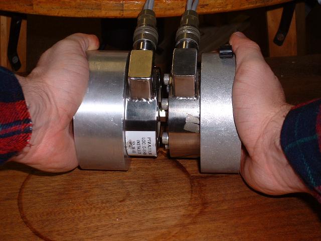
The improvement in this test was to replace the 50lbs Lebow load cell with two nearly identical Sensotec/Daytonic100lbs load cells. The load cells used were dictated by three things, the Sensotec hysteresis performance which was excellent in previous test runs, by budget and lastly, by availability in the eBay second hand market.
As shown in figure one, a serial compression test was done to check if the linearity of each load cell was the same. Even though the load cells are capable of 100lbs, the test was only done up to 25lbs, which is a broad enough range to cover the expected data.
Figure 1: Serial Test of Load Cells
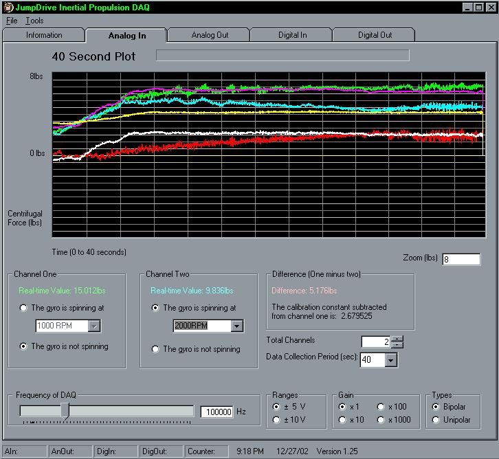
As the results show in figure two, the load cells have the same linearity over the expected range. It should be noted that the no-load reading on each load cell was ~3.8lbs which will be calibrated to zero before the baseline and primary results are taken which can be confirmed on the screen shots in the "difference" box where it says "The results are ..."
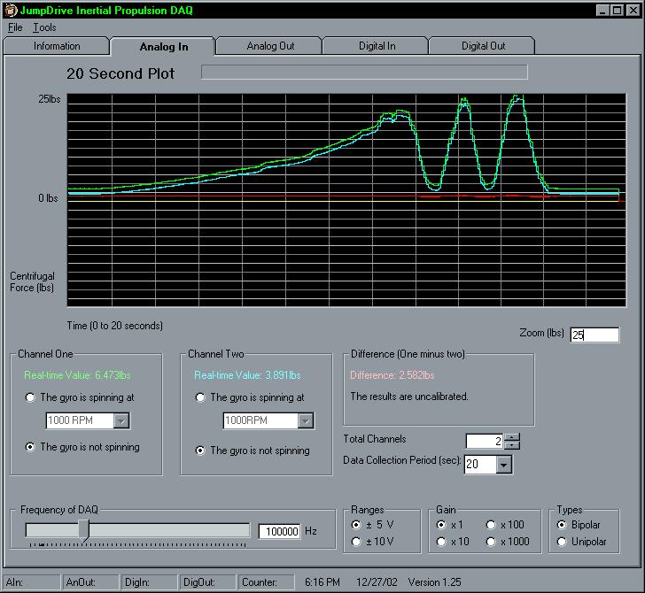
Figure 2: Screen Shot of Serial Results
As before, care was taken in making sure the apparatus was balanced completely around the circumference, as shown in figure three.
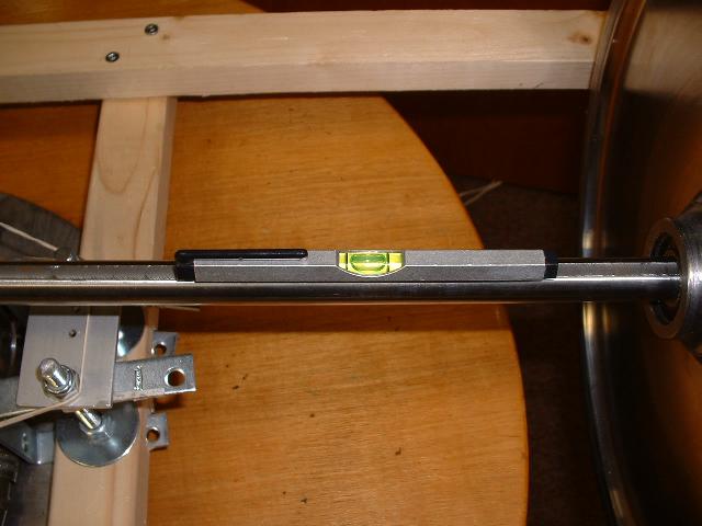
Figure 3: Balanced
The software was also updated, now version 1.25, to account for the 100lbs load cells (changed a constant and recompiled).
See Initial Results for a description of the variable types in the baseline and primary results.
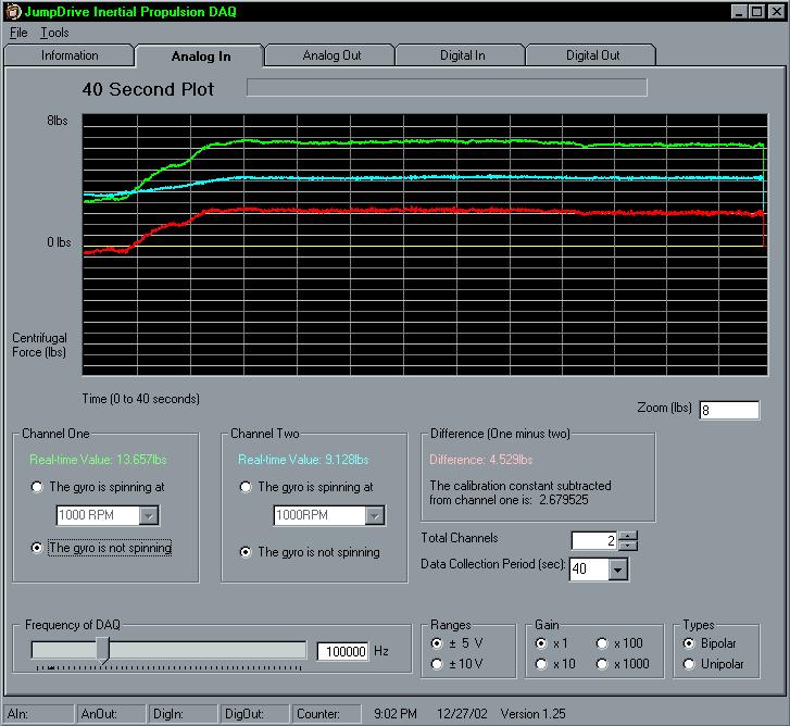
3. Baseline Results
These results correspond to step 3 in the description and are run with the following static variables:
Note: This was chosen because when channel two measures that force, a 3000RPM gyro is off it's rest and can provide an easy baseline.
Raw Data: "C1 - B_7_0_01.txt"
(Contained in "Baseline Raw Data.zip")
Note: B_7_0_01 shows that the two load cells are measuring an
increasing difference when the platform is accelerating.
Raw Data: "C1 - B_7_0_02.txt"
(Contained in "Basline Raw Data.zip")
Note: B_7_0_02 is used to compare against the primary results.
4. Primary Results
For all the primary results, the following static variables apply:
Gyro Variable, Channel One Gyro 3000RPM - G_1_0_04
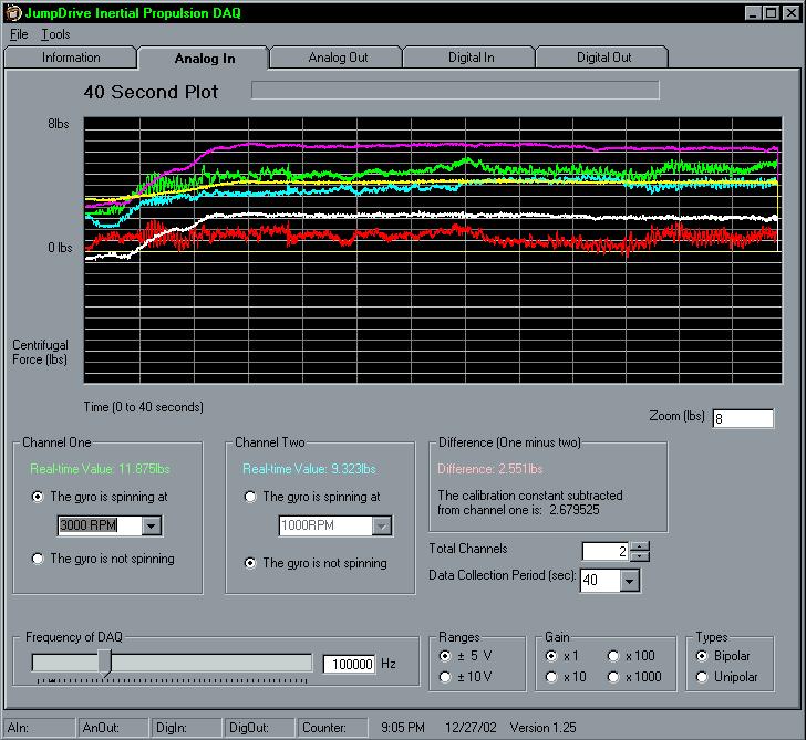
Raw Data Filename - "C1 - G_1_0_04.txt" (Contained in "Raw Data for Gyro Variable.zip")
Gyro Variable, Channel One Gyro 2000RPM - G_1_0_05
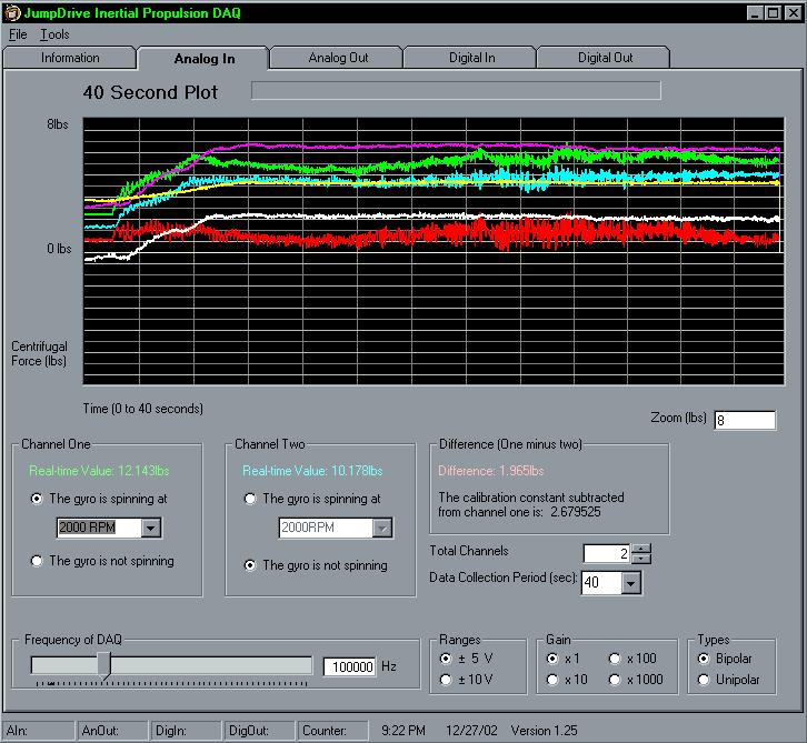
Raw Data: "C1 - G_1_0_05.txt" (Contained in "Raw Data for Gyro Variable.zip")
Gyro Variable, Channel Two Gyro 3000RPM - G_2_0_04
Note: This channel contains the gyro which was balanced.
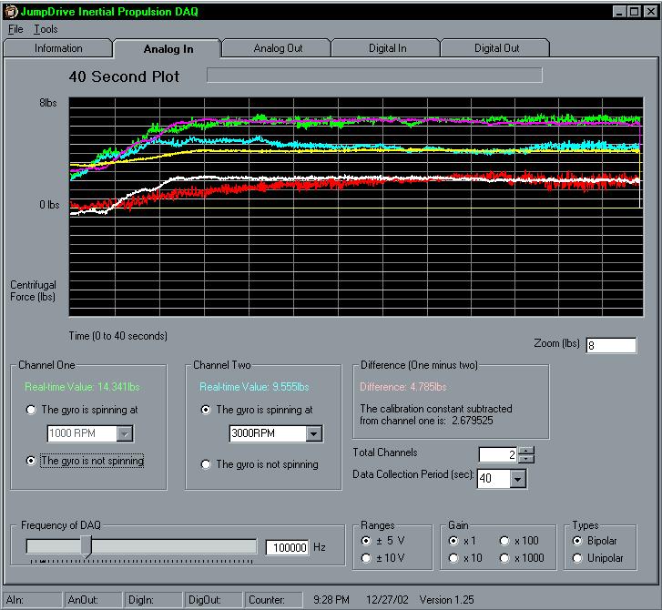
Raw Data: "C1 - G_2_0_04.txt" (Contained in "Raw Data for Gyro Variable.zip")
Gyro Variable, Channel Two Gyro 2000RPM - G_2_0_05
Note: This channel contains the gyro which was balanced.
Raw Data: "C1 - G_2_0_05.txt" (Contained in "Raw Data for Gyro Variable.zip")
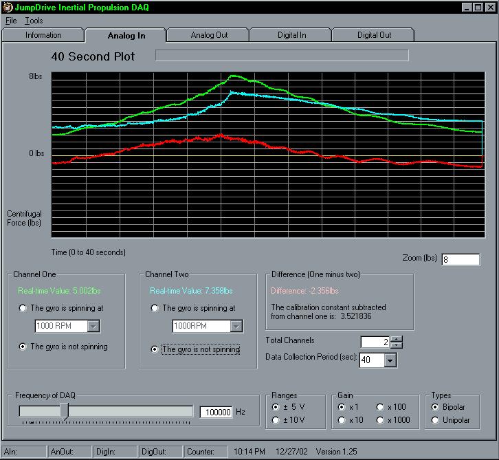
5. Analysis
As the data shows there is a difference on channel one, but none on channel two, in other words, for channel two the blue line should be below the yellow when the green line is on top of the purple line.
The channel one results are interesting because there is anecdotal evidence that the higher speed, 3000RPM, increased the difference between the primary and the baseline.
As a critic, there are still problems with the setup and again the load cells are the source. The first is that the load cells still have differences between them. The type of load cells that seem to work the best are worth �700 each which puts them outside of my budget, especially if I am changing focus in the short term. I can get second hand ones from eBay, but it means I am at the mercy of what is available in regards to quality and required characteristics. In the last batch of load cells I found, I managed to get three 100lbs load cells, two Daytonic and one Sensotec. Unfortunately one of the Daytonic load cells registered a no-load of 18lbs which left me with the Sensotec and Daytonic load cells and those two, thank goodness, registered the same no-load result which can be calibrated for.
The labeling on the graph is also messed up because the 8lbs is more like 16lbs.
One possible explanation for the LaithwaiteDawson effect could be described by a rocket moving around a circle analogy. The gyroscope is moving itself around the circumference.
Description | Setup | Initial Results | Next Results | 12" Gyro Results | Next 12" Results
C1 Results | Next C1 | Final C1
JumpDrive Confidential, 2002 - All right reserved, no part of this document may be reproduced without the authors permission.